Hey, guys. Sorry for the incredibly long period of silence. I got really busy with my personal life. I finally have time for DIY fun, though, and I already have a few big projects to show you all. In fact, my next project on here is going to involve the ever-so-popular video game, Desert Bus!
Here’s a quick and easy one for you all. I found my turntable recently, just in time for my copy of the new Daft Punk album to arrive in the mail. While listening to it, I decided that I wanted to post the album art on my wall, but I didn’t want to risk any adhesives or tacks damaging my precious albums. I thought about building a shelf or a bookcase, but I also happened to be lazy and low on cash.
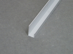
After browsing Home Depot aimlessly for a while, I found myself looking at wall trim. I found a strip of 1/2 in J trim and almost squealed in joy, in a tough and masculine way, of course. This was exactly what I needed, and would only run me $7 for 12 feet of the stuff.
Perfect!
The plan was fairly simple. I would cut the trim into 3 inch pieces, drill two holes on the long side of the trim, and then mount them on my wall using wood screws. I would need two pieces on the bottom to hold up the vinyl, and then one piece on top to keep it from falling over. The half inch trim would be big enough to hold even a double album, but small enough to stop single albums from moving around too much.
A three inch piece, with the two holes drilled in.
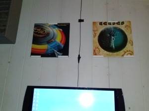
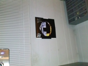
I put up 11 albums this way before deciding that I had enough for the time being. I still have enough pieces left to put up about four or five more if I want to.
Here are some images of my walls, decorated by some of my favorite pieces of album art.
The best part about this setup is that if I want to replace an album with something else, or listen to one of them, it slides out easily. The record is completely unharmed, and I can easily slide it right back in.
Hello! It’s the moment we’ve all been waiting for. This past Saturday, I hooked everything up at i3 Detroit, and we played a couple of rounds of Artemis with the SaikoLED providing the neat dramatic effects we were looking for. Check out the video below!
Once again, huge thanks to Brian Neltner of SaikoLED, fellow i3 Detroit member Andrew, and i3 Detroit itself for making this project possible. I hope to have many more great projects to show you all soon, but this will be one of my favorite ones for a very long time!
Alright, time for my first non-SaikoLED/Artemis post!
I received a comment on my Youtube channel asking for the code to one of my absolute favorite projects so far.
Featured below is a commercial for the Philips Ambilight technology. This is an absolutely fascinating feature on new TVs that actually lights up the area surrounding the screen, based on the most prominent color currently being shown. Note the use of purple/green that they demonstrate for The Hulk.
I was overjoyed when I discovered that there was an existing DIY Ambilight clone featured at http://www.lifehacker.com.
Basically, a hobbyist by the name of Rajarshi Roy had created this clone by writing his own screen capture software in Processing, and then using that to send the color data to an Arduino, which then drove a strip of RGB LEDs. He used a strip that was being sold at SparkFun’s website. I have an inexplicable dislike of ordering things online, so I decided to eat the extra cost and buy a Radio Shack RGB LED strip. This was, possibly, the worst mistake I could’ve made.
The SparkFun strip used four wires and was very well documented. The Radio Shack strip used three wires, and was incredibly confusing with no documentation whatsoever. I used Rajarshi’s Processing code and Arduino code at first, as a base point. Of course, it didn’t work. It wasn’t written for the hardware that I used. I then modified Radio Shack’s example code, which sent hex values to the ICs that drove the RGBs. It then used timed pulses to push data across the strip, lighting them up with the specified color. I don’t know this because it was in the documentation. I know this because I spent an entire night/morning reading through it and barely grasping the concept. I still don’t have a concrete idea on how it works. Instead of advertising it as a DIY component, they should honestly just say “Radio Shack – 1 Meter RGB LED Bright Flashing Rainbow Strip”, as that’s all the default code does.
I cut out all of the bits of code that sent all of the pretty colors, and then took bits of Rajarshi’s code and plugged them in. I made progress! The lights came on and actually reacted to the computer. However, everything was pink. No matter what I did, everything was pink. I gave up for the night, and literally woke up four hours later with the answer popping into my head. The values are reversed. It’s not an RGB strip. It’s a BGR strip. I swapped the values around a little and tried again…
Ohhhhh yeah. I then decided to test it out using Winamp’s visualizer, and the DI.FM Epic Trance broadcast.
BEAUTIFUL. I loved it! To this day, the Arduino and RGB strip are permanently mounted behind my TV. It’s excellent for movies and video games (Seriously, firing the Plasma Gun in Quake 3 is so much fun. The whole room lights up.)
I’ve attached the two files I used below. The Arduino code (Named strip_1m.ino because I never bothered to rename the Radio Shack file), and the Processing code. Enjoy!
QUICK NOTE : I do NOT take any credit for the hard work put behind Rajarshi Roy’s work. All I did was make the program play nice with the Radio Shack RGB strip. If you’d like to thank anybody, thank the man himself right here.
Also, please keep in mind that you’re going to need both Processing, found at http://www.processing.org/
I switched to store-bought converters, rather than making my own. It did not work.
I was stumped. I was certain that I uploaded the correct code to the SaikoLED. I was certain that I was using the correct wires on my ethernet cable. But I wasn’t certain of anything else. Was the cable actually good? Was the software actually outputting anything? Was I converting the signal correctly? Was the unit itself working? I gave up on trying to finish the project on my own and took the next logical step. I went to i3Detroit and asked for a second opinion.
I met up with fellow hackerspace-member Andrew. He was very willing to help me figure out what was wrong. The first thing we did was rebuild the conversion cable, testing it with an oscilloscope and Artemis itself to make sure that serial data was being output. It was. This was excellent news, as we were now able to narrow the problem down to the unit itself.
Were the switches in the right position? Yes. Was the cable plugged into the right port? Yes. Was it getting power? Yes. Andrew then looked over the schematic, realizing something after a few times through.
There’s a component missing! Furthermore, this is the component we needed to send the DMX signals to the Arduino. We were able to find a spare one and solder it on.
We put it back inside of its enclosure and started everything back up. After clicking ‘Start Game’ in Artemis, the light suddenly came on! We had a white light filling the room! After cheering and jumping around, we exit Artemis and booted up Madrix. The results of that can be seen below, as Andrew controls the program to output various colors to the LED, using DMX.
All that’s left to do is mount the unit permanently inside our gaming area, and record some gameplay footage. Stay tuned for my final SaikoLED update!
I came home today to find a package waiting for me. Since I haven’t ordered anything recently, I realized that it’s more than likely the prototype MyKi light. Feeling like a kid on Christmas, I quickly opened the package and gazed upon the metal encased beauty before me.
Okay, so right off the bat, I’m incredibly impressed with the build quality. I would feel perfectly comfortable mounting this on a wall or ceiling in our gaming area at i3Detroit. I then looked along the sides of the case for any inputs that I should be aware of. I couldn’t believe how much I lucked out.
I wasn’t entirely sure what those ports were. I assumed it was some kind of network control for the unit. Looking at the board, however…
DMX INPUT. I didn’t have to do anything! All I need to do is find the appropriate cable at the hackerspace (Probably USB to RJ485). This project just became ten times easier. In fact, I can probably wrap everything up by Thursday, or perhaps even tomorrow if I stop by i3Detroit in the afternoon.
Now, how does the light look when it’s plugged in? Is it bright enough? Are the colors vibrant enough to be noticed? I gave Brian Neltner over at SaikoLED a call before plugging it in, making sure that I was feeding it the right amount of power. Winds up that it runs just fine off of standard Micro-USB, such as that on an Android phone charger. I plugged the device in, and was incredibly happy with the result. This thing is bright! I was nearly blinded when I looked into it while plugging it in. I then set it on the table and let it run through its demo mode, realizing just how perfect this light is for our Artemis sessions.
I uploaded a video of the light in test mode. Watch it below.
Update : I completely forgot, but this thing is also sound activated while running the default code. Check it out below!
I was picked as a winner of the competition because I said that I would create some wicked custom lighting for the game “Artemis : Bridge Simulator”. “But what IS Artemis?” you ask. Since I just had a session of the game last night at i3Detroit, I figured I’d type up a quick post explaining the game and why it’s perfect for a DIY enthusiast. This way, when the project is complete, my readers will be able to appreciate it even more.
“Artemis is a multiplayer, multi-computer networked game for Windows computers, and now IOS devices too.
Artemis simulates a spaceship bridge by networking several computers together. One computer runs the simulation and the “main screen”, while the others serve as workstations for the normal jobs a bridge officer might do, like Helm, Communication, Engineering, and Weapon Control. Artemis is a social game where several players are together in one room (“bridge”) , and while they all work together, one player plays the Captain, a person who sits in the middle, doesn’t have a workstation, and tells everyone what to do.”
Basically, it’s a Hollywood Sci-fi simulator. We currently play in a small area with a couch, a couple of chairs, and two tables. A projector and screen are installed into this small area, and the lights are turned off before play. On its own, it’s pretty nice. The couch is really comfortable, and with the lights off there’s still a pretty good atmosphere to play in.
The DIY aspect lies in two important details. As I mentioned previously, the game supports DMX output. This game was pretty much made for bright dramatic lighting and fog machines. The second thing is the fact that it’s actually fairly easy to create custom USB controllers. After the lighting is finished, we have plans of making custom control panels such as a weapons station with a big, shiny red “FIRE” button.
After the MyKi project, you might see an occasional Artemis post as I make something really cool to fit into i3Detroit’s play area. I’m looking forward to sharing some great projects with you all soon.
With the light and power supply on their way, I decided to begin immediately. While the last Artemis lighting project used an RGB strip, and the ship’s in-game data being sent over OSC, I want to use the actual DMX commands this time. I feel that it would be far more stable, and much easier to expand on if I wanted to add anything else down the line.
The first thing I needed to do was find a way to deal with Artemis’ DMX output. The easy way would be to purchase the ENTTEC Open DMX Usb Interface. However, I’m cheap, and would rather not be set back $70 right now. So instead, I decided to take advantage of the fact that it’s open hardware. I researched schematics and datasheets until finding out that DMX information is actually transmitted via RS485. So the task was no longer ‘Turn a USB cable into a DMX cable’. It was now ‘Find a way to convert USB to RS485’. This was the first step in the right direction.
The thing I love about i3Detroit, and hackerspaces in general, is that there’s always boxes of stuff laying around. Anything you want, you can either find it, or find the things you need to make it. I was able to find a cable that went from USB to RS232, and then a box that would convert RS232 to RS485. I was in business! I borrowed the cables and went home to begin working on everything.
The most important rule about any tech work in general, for me at least, is that things will never correctly work the first time. I’m not complaining, or whining about it. It’s just how things work. I see it as more of an interesting challenge than an obstacle. The cable I borrowed is not compatible with Windows 7 64 Bit. This is only a minor setback, however, as I only need to go back to the hackerspace and try another cable. Unfortunately, until Thursday this project is on standby. Luckily, I should have the prototype light by then and I can then handle everything in one quick sweep.
About a month ago, I entered the SaikoLED MyKi challenge. The idea behind the challenge was to get various hobbyist groups and hackerspaces involved with this new lighting system that was being released. Each group suggests their idea to the company, and three winners would receive a prototype of the MyKi light to tinker with, under the condition that they would document the process and provide plenty of neat pictures and videos. I made this blog specifically to document my contest-winning project.
My idea for the project stems from a bi-weekly event that already takes place at my hackerspace of choice, i3Detroit. Every other Saturday, a small group of us would get together and network our laptops together in a small room with a projector to play the video game Artemis : Bridge Simulator. While I won’t go into the full details of the game, there’s one little thing that makes Artemis the perfect hackerspace game. It’s just begging for DIY enthusiasts to make custom hardware for it.
I discovered that the game natively outputs DMX signals, similar to what would be used with stage shows and DJ lighting. I got very excited about this, and quickly searched for a cost effective way to rig up some DMX lighting at i3Detroit. The problem was in the cost effective part. DMX lights ran from about $50 a piece, at the minimum, and the OpenDMX USB interface that was suggested ran $70 + shipping. I wanted something even more affordable. So, I searched through the equipment I already had.
The result was an RGB LED strip that was controlled using the ship’s in-game data file, rather than the DMX commands. It was buggy, it crashed frequently, and as nice as it looked, it simply wasn’t bright enough to be noticed during gameplay. To make matters worse, the latest Artemis update didn’t work at all with this method. I put this project on the backburner and moved onto other things. It was then that I found out about the MyKi contest. Realizing that this light would be absolutely perfect, I quickly submitted my idea, excited about mounting this light in our Artemis play area at i3Detroit. A few weeks later, I received the thrilling news that my hackerspace was chosen. The prototype is on its way!
I immediately began work on the project, and also decided to document it every step of the way, to keep up my end of the deal with SaikoLED. The next few blog posts will track my progress with the Artemis lighting project, and will hopefully conclude with an awesome video of everything in action. Stay tuned for more!